CHF 2,278.00
CHF 2,278.00
excl. VAT
Available: 1.0 Units
This combination does not exist.
Units of Measure: Units
Add to basket
Warranty conditions
12 months manufacturer's warranty from date of delivery.
The warranty expires if,
- The installation is not carried out by a qualified professional.
- The pump is opened or otherwise tampered with.
- If the wrong or contaminated operating materials are used.
The LT-Shop is not responsible for assembly and disassembly.
Product information:
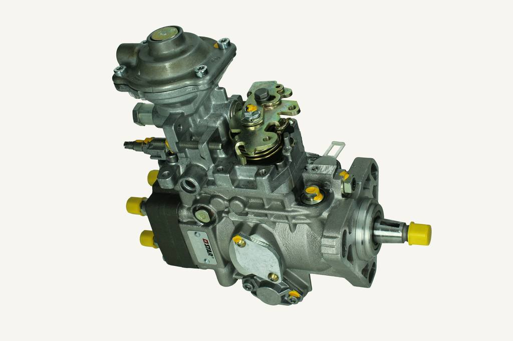
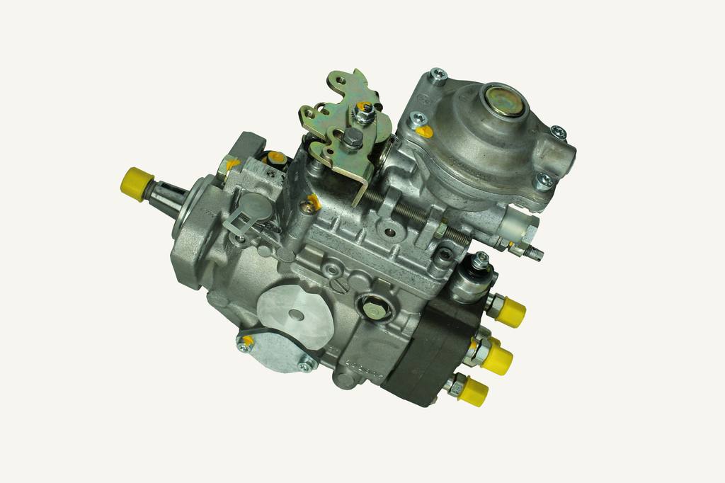
VEL678TD
TL100 up to engine number 776978 0460414137
TL100 from engine number 776979 0460414171
Non-reduced emission engines 8045.25K213
Injection start 7°+/-0.5° before TDC (PMS Punto Morto Superiore) TDC top dead centre) =OT
(dial gauge 1mm stroke)
Diagnosing an out-of-round engine run on a TL-SERIE
1. check the fuel inlet line for obstructions. This can be done in many different ways, but the quickest and most accurate method is to check the entire intake system by installing a low pressure gauge on the banjo screw at the inlet of the injection pump. There should always be positive pressure at that location; the pressure should be about 6 to 10 PSI at full throttle and full load. If the gauge goes to 0 at full throttle and full load, then the problem is in the fuel inlet side of the system. 2.
Check the fuel to be sure it is not contaminated. Run a short pipe from the small transfer pump into a can of clean fuel. Run the tractor with this fuel supply and compare the performance. 3.
Check the air intake for obstructions. 4.
4. remove the thermal starter and check for fuel leakage.
5. check the banjo bolts on the injection pump inlet and return lines to ensure they are properly installed. The banjo bolt with the small orifice hole must be installed in the return line i.
Check the injection timing using tool numbers 380000228 and 380000229. 7.
Pull the four injectors and check the injection pressure and pattern. 8.
Remove the injection pump and have it inspected by an authorised Bosch service centre. Explain the engine problems in detail to the Bosch service centre and ask that the pump be completely disassembled and all components inspected, especially the cold fuel injection piston.
9. check the intake and exhaust valve settings and adjust if necessary according to the repair manual. 0.30mm
10. carry out a compression test. Repair according to appropriate recommendations in repair manual. See the engine section of the repair manual for detailed instructions on the compression test procedure and expected results.
IMPORTANT: Engine speed fluctuations at low engine speeds are not recognised or perceived as a problem by all drivers.
If the tractor problem is an engine speed fluctuation or a fluctuation of less than 50 rpm with the engine at low idle (800 to 1300 rpm), go to step 14. Fluctuation of less than 50 rpm with the engine at low idle is not a result of parts adjustment or failure.
If the engine speed fluctuation or low idle fluctuation is greater than 100 rpm, the cause can be found by checking the following steps 1 to 13. 1.
1. check the entire fuel supply line for obstructions. This can be done in many different ways. The quickest and most accurate method is to install a low pressure gauge on the banjo screw at the inlet of the injection pump.
- There must always be positive pressure at this point. Approximately 0.41 to 0.69 bar (6 to 10 PSI) at full throttle.
- If the gauge reads 0 at full throttle, the problem is on the fuel supply side of the system. 2.
Check the fuel supply for contamination. Place a short line from the small transfer (mechanical lift/suction) pump into a container of clean fuel.
- Run the tractor with this supply and compare the performance.
- Remove the top cover of the transmission pump and check the screen for debris. Clean the connector as found. 3.
Check the high (2750 rpm) and low (800 rpm) idle settings.
- Ensure that the tamper-proof nuts are reinstalled after adjustment.
Check the air intake for obstructions. 5.
Remove the thermostart and check for fuel leakage. 6.
6. check the banjo bolts on the injection pump inlet and the return lines to ensure they are properly installed.
- The banjo screw with the small opening hole must be installed in the return port. 7.
Make sure that the pointer in the flywheel adjustment cover hole is correct and points to PMS on the flywheel (PMS represents top dead centre). True engine top dead centre can be achieved by:
- Removing the fuel injector in cylinder number one (front).
- Remove the flywheel adjustment hole cover and turn the flywheel until you see PMS (represents top dead centre) at the end of the pointer.
- Install a dial indicator with a magnetic base and a shaft long enough to reach the top of the piston above the number one injector hole.
- Turn the engine backwards a few degrees to move the piston away from the dial gauge.
- Then turn the engine forward to bring the piston up towards the dial gauge.
- When the dial gauge needle stops moving, continue to turn the motor until the dial gauge needle starts moving again.
- Half the distance between the point where the needle stops moving upwards and the point where it starts to sink is the true top dead centre for piston number one.
- When the engine is turned to this point, the pointer in the flywheel adjustment hole cover must point directly to PMS (represents top dead centre).
- If it does not point directly at PMS, carefully bend the pointer so that it points at PMS. If the pointer is bent out of position, it will cause an error when checking the setting in step 8. 8.
Make sure that the fuel injection pump timing settings match the specifications.
- The Robert Bosch, Model VE fuel injection pump adjustment tools (part numbers 291755 and 291754) are sold as a tool kit (part number 380000229). These tools were previously sold as an assembly kit part number NH01393. They are also offered by Snap-On with tool number YA8331 (dial gauge and thread adapter). 9.
9. remove the four fuel injectors and check the gap pressure and the spray pattern. 10.
Remove the fuel injection pump and injectors. Have them checked by an authorised Robert Bosch Service Center.
- Explain the engine problem in detail to the service centre personnel servicing the fuel injection pump and ask that the pump be completely disassembled and all components checked. This applies especially to the governor springs, low-load governor springs, governor pivot points, flyweights, gauge sleeve and associated parts.
- Injection pumps and injectors must always be checked together as a set. 11.
11. remove the valve cover and check the intake and exhaust valve clearances and valve adjustments, if necessary.
12. remove each injector and carry out a compression test for each cylinder. Minimum compression is 20 bar (290 psi). The change from cylinder to cylinder must not exceed 3.4 Bar (50 Psi).
13. after all checks have been carried out and the engine is still oscillating at less than 50 rpm at low idle (800 - 1300 rpm), proceed as follows:
14. if the tractor is part of a dealer's stock, do not invest time or money in overhauling or replacing the engine.
- The symptom is caused by changes in engine tolerances during assembly of the engine.
- Similar symptoms or problems may also occur with a replacement engine.
- The symptom (50 rpm fluctuation) does NOT occur above 1300 rpm and on most tractors it does not occur above 1000 rpm.
- Contact your local CBU Technical Service Centre if there are any other problems related to this. 15.
15. If the tractor is an end-user unit, explain the details listed in step 14. If the customer continues to insist on a solution, contact your local CBU service and sales representative.
- At this time, only TL90 tractors have been reported with the problem. The symptom (50 rpm fluctuation) can be detected visually (speedometer needle), heard (misfire) and touched (vibration).
- The problem has not been reported on the TL100 and TL80. The symptom is audible but not associated with speed fluctuation or vibration.
Checkout


