CHF 459.20
CHF 459.20
excl. VAT
Available: 1.0 Units
This combination does not exist.
Units of Measure: Units
Add to basket
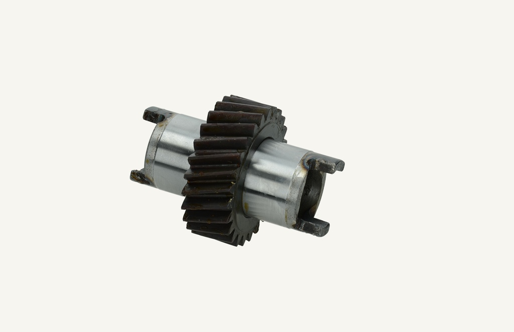
Zähnezahl: 25
Die Haltbarkeit der Antriebswelle 98465572 der vom Motor angetriebenen
Hydraulikpumpe wurde verbessert.
Die verbesserte Antriebswelle der vom Motor angetriebenen
Hydraulikpumpe wurde ab Seriennummer: 698502 in die
Produktion eingeführt.
98465572 Zahnradwelle Verstärkt
84420573 Zahnradwelle Standard
Um dieses Zahnrad zu ersetzen, muss der Stirnraddeckel vorne weggebaut werden, da die Zahnung der Zahnradwelle 84420573 (Ø 66.5mm) grösser ist als die Bohrung im Stirnraddeckel ( Ø 58mm)
Product information:
98465572=Made in Italy
84420573=Made in Turkey Nitrided-Oxidised
Oxidising the workpieces can be carried out as a separate process or ideally in combination with nitriding. Depending on the steel quality, oxidising produces an anthracite-black surface and has the advantage of protecting the workpieces from corrosion.
The oxide layer is 1 - 3 µm. Oxidising also improves the sliding and friction properties.
Attention Check clearance in the bearing bushes Bearing bush dimensions 37.05 to 37.075mm
To replace this gear, the spur gear cover must be removed at the front, as the teeth of the gear shaft (Ø 66.5mm) are larger than the bore in the spur gear cover (Ø 58mm).
Defective drive gear has a cause !
Check the directional control valves to see if the neutral position works and check if the pressure limit switch works!
Attach a pressure gauge to a plug-in coupling of the rear auxiliary control valve. Check the max pressure while running the system against overpressure (DBV). The reading must be between 185 and 191 bar.
After repairing the tractor, temporarily insert a 0-345-bar pressure gauge into the small test port located on the pressure oil line of the main hydraulic pump. The connection has thread size M12 x12.5mm. Observe the pressure gauge while the customer is operating the tractor in the normal way. When operating the tractor without using auxiliary hydraulic functions, the circulation pressure reading should not rise above 27 bar. The pressure gauge should not indicate overpressures above 165 bar during use of hydraulic functions. Any excess of these readings is an indication that the hydraulic system is operating at overpressure due to the customer's method of operation.
When using a rear auxiliary control valve to supply a hydraulic motor, make sure that the motor is large enough to receive the entire oil flow from the main pump. If the motor is too small to take all the oil flow, pressure will build up between the main hydraulic oil pump and the hydraulic motor. When the pressure has risen to approximately 176 bar, the high-pressure relief valve opens (provided the relief valve is set correctly). The pressure will continue to rise up to 207 bar. At this point, all the oil pumped by the main hydraulic oil pump will flow through the pressure relief valve into the main hydraulic oil filter. This oil then flows in a circuit back out of the filter, into the pump, out of the pump and through the relief valve. The oil, which constantly flows through the pressure relief valve, overheats and causes excessive stress on the pump drive clutch. This eventually leads to a defect in the pump drive shaft, the coupling or the bearing bushings.
The rear auxiliary control valve no. 1 is with pressure end cut-off. This means that the lever remains engaged in one of the pressure positions until the pressure reaches 170 to 175 bar. At this value, it then jumps to the "neutral" position. If the lever does not jump out of the pressure position and return to the neutral position, check the control lever pivot and cable to make sure they can move freely without obstructions. If the lever and cables do not jam, the cut-off pressure adjustment screw, located under the detent assembly, is not properly adjusted.
During assembly, make sure that the two dowel pins (part number 10839610) are properly installed in the rear half of the front cover (part number 99469836). The dowel pins will protrude from the cover approximately 6.3 mm (0.25 inch) and snap into the front cover (part number 4769749) during assembly. The two dowel pins ensure that the hydraulic pump and drive shaft maintain proper alignment.
Checkout