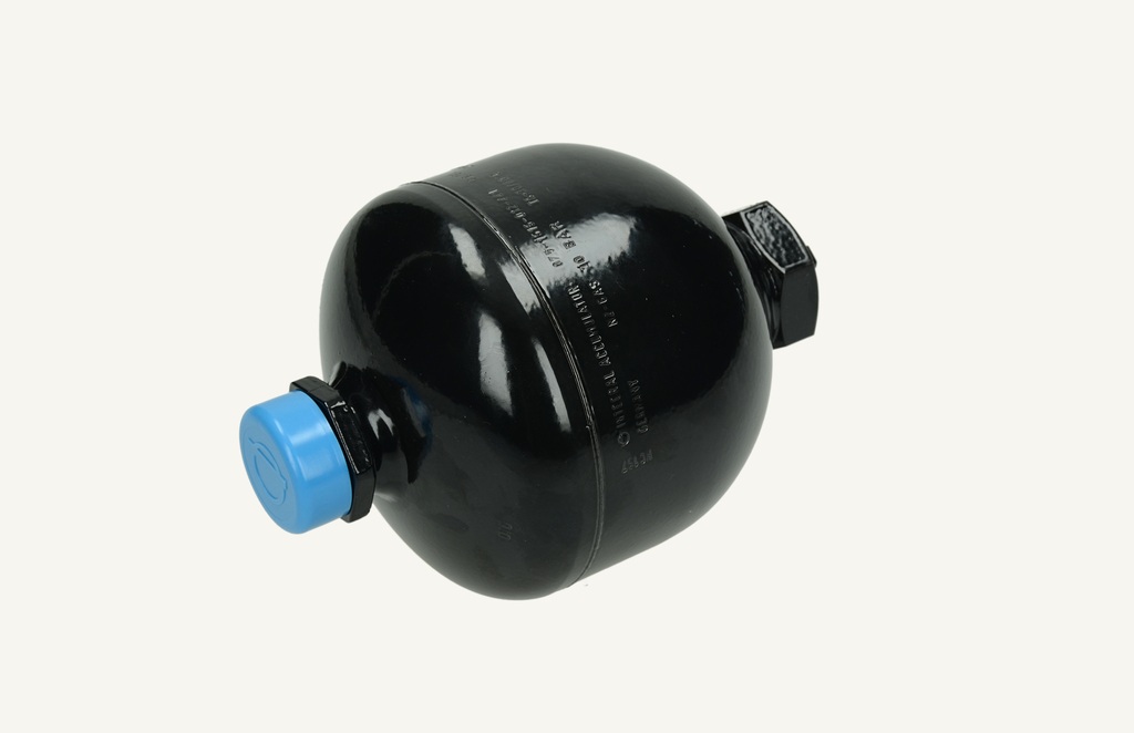
CHF 293.15
CHF 293.15
excl. VAT
Available: 1.0 Units
This combination does not exist.
Units of Measure: Units
Add to basket
Charging pressure 10 bar +/-1 bar at 20°C
Volume 0.75 litre
Product information:
Check the pressure of the nitrogen charge in the transmission accumulator and, if necessary, reset it to 10 bar.
To check the pressure and to charge the accumulator, it is necessary to use the special tool 380000327.
Properly charged accumulators are necessary when transmission changes are made and multiple clutch packs are used. If nitrogen pressure is low, there will be a drop in oil pressure resulting in faulty transmission shift quality.
The pressure accumulators 5195043 are charged with 10 bar at 20 °C. These are the pressure accumulators for the transmission, brakes and front hitch.
Use the appropriate tools to check or charge the transmission pressure accumulator.
Technical data for the transmission pressure accumulator (part number 5195043) are as follows:
Septum.
Nitrogen charge capacity = 0.7 litres (0.739 qts)
Charge pressure = 9 to 10 bar (130.5 to 145 psi) at 20 degrees C (68 degrees F).
The charging tool, part number 380001737 or CAS10899 (with regulator) or CAS10088A (without regulator) is designed to be connected to a shrader valve (tyre valve). The transmission pressure accumulator (part number 5195043) has a metric fit with a plug that requires a hex spanner for removal. This fitting does not work with the existing filling tool.
The adaptor (part number 380001168) can be screwed onto the accumulator and has a shrader valve on the side so that the existing charging tool can be used. If the shrader valve is not accessible when the adapter is tight to the accumulator, rotate the entire accumulator to gain proper access to make the connection.
Accumulator filling pressure specification:
Part number 5195043: 130.5 to 145 psi (9 to 10 bar) at 68 degrees F (20 degrees C).
To charge the transmission accumulator, part number 5195043, use accumulator charging adapter 380001168.
Note: This accumulator (part number 5195043) and other units with the same type of fit can be charged with this tool.
Filling the pressure accumulator for the spring-loaded axle
To charge the pressure accumulator (part number 5195043) for the transmission, use the accumulator charging adapter (tool part number 380001168).
The accumulator charging hose (tool part number 380001390) is required to connect between the socket side from the regulator valve on the nitrogen tank to the matching side from the accumulator charging valve.
The nitrogen regulator valve (tool part number 380001676 or CAS10899-1) is required to adjust the nitrogen tank pressure to the specified charge pressure.
1.Remove the protective cap on the top of the pressure accumulator. Look for the hexagonal Allen key under the protective cap.
2.Pull out the inner square on the top of the adapter. Screw the adapter onto the pressure accumulator as far as it will go. Slightly unscrew it again and push the inner square down to engage the hexagon socket on the inside of the tool with the hexagon plug in the pressure accumulator. Tighten the adapter by hand.
3.connect the accumulator filling hose and the control valve to the filling valve on the accumulator.
Troubleshooting poor brake performance - TM/MXM
Poor braking performance
Excessive brake pedal play when applying the brake.
This only applies to TM175, TM190, MXM175, MXM190 with a power brake system.
Check the brake system for part failure that may be causing the leak.
If an external leak is detected, investigate and repair the cause of the leak.
If the oil leakage is from the brake master cylinders or if no external leakage is detected, perform a pressure test on the brake system.
If the brake master cylinder is the cause of the leak, check the operation of the brake pressure accumulator (part number 5195043) before installing a new master cylinder.
The pressure accumulator is filled with nitrogen and compensates for pressure peaks in the brake system before they reach the check valve. An empty accumulator will cause pressure spikes to enter the brake system and will be felt in all components in the brake system.
This causes cracks in the master cylinder and eventually its failure. Cracks form in the body of the master cylinder between the two holes that allow fluid to flow from side to side or exit the master cylinder through the side wall of the master cylinder.
The accumulator must be replaced or refilled before the new master cylinders are installed.
Test the servo brake supply and pressure accumulator.
The servo brake system supply, accumulator and check valve can be checked for proper operation as follows:
Remove the low pressure warning switch from the manifold and install adapter 380000577 with quick connector 380000492.
Connect a 40 bar (600 psi) gauge 380000552 with quick connector 380000543 and hose 380000545.
Start the engine and run it at 1500 rpm.
Depress the brake pedal and observe the pressure gauge. The pressure may fluctuate slightly, but must remain at approx. 22 -24 bar (319 - 348 psi).
Switch off the engine and observe the pressure gauge. If the check valve on the distributor is working correctly, the pressure must remain at approx. 22 -24 bar (319 - 348 psi).
Note: If a gradual drop in pressure is indicated, the master cylinder may be leaking internally or a brake piston may be stuck. To confirm that a fault is occurring within the master cylinder, close the supply to the master cylinder from the accumulator / manifold assembly and repeat the test. If the pressure remains constant with the supply line closed, this indicates a fault in the master cylinder.
Turn the ignition key to the OFF position, depress the brake pedals. If the pressure accumulator is working properly, the system will lose approximately 1 bar (14.5 psi) each time the brake pedals are operated.
Note: The low brake pressure warning switch is set to 15 bar (218 psi).
Checkout
